Baidu Baike defines the step Angle as the mechanical Angle at which the rotor of a stepping motor rotates each time it receives an electrical pulse signal. If half-step and subdivision are taken into account, then this description might not be very accurate. The definition of the step Angle of a stepper motor in the book is: when the stepper motor switches the excitation current of the stator winding once, the rotor rotates a fixed Angle, that is, the step Angle. This description is more accurate. Here, switching the stator winding once should refer to "switching" from one connected state to another.
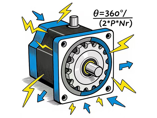
The step Angle is determined by the physical structure of the motor, mainly depending on the number of phases P of the stator winding and the number of pole pairs of the rotor (for VR stepper motors, it is the number of teeth) Nr. The calculation formula is:
Step Angle θ=360°/ (2*P*Nr)
At this point, some friends may ask: Can't the stepper motor be subdivided simply by driving it? Wouldn't the accuracy or resolution be higher if it were subdivided several more times?
If you think this way, it seems there's no need to bother with a 50-tooth rotor to make a 1.8° step Angle. Why not just make a 30° step Angle for subdivision? In fact, this step Angle can be regarded as the factory resolution of the stepper motor, and the subdivision is what is called "anti-aliasing technology" (gamers should all know this, right?). The step Angle is a physical characteristic of the motor itself and is the "underlying logic" of the resolution of a stepper motor. Subdivision is achieved by controlling the strength of the electrical signal, and in terms of accuracy, it cannot be guaranteed. From the perspective of signals, the step Angle is achieved through the "on/off" of the current, that is, 0/1, which belongs to the execution of digital signals. Subdivision is controlled by the variation in the strength of the current and belongs to the execution of analog signals.
Then why does the step Angle depend on the number of phases in the stator winding and the number of stator pole pairs, and why is it θ=360°/ (2*P*Nr)? Here's how we understand it:

First, let's talk about the number of stator phases P. The stator has P phases, and each phase has two directions of conduction. Therefore, the number of basic magnetic field states of the stator is 2P. For example:
For A single-phase stator, whether it has two windings, four windings or 2N windings, since there is only one wire, there are only two states, A and A-.
For A two-phase stator, whether it has 4 windings, 8 windings or 4N windings, since there are only two wires, there are four magnetic field states: A/A-/B/B-.
Why is it emphasized as the basic magnetic field state (only the magnetic field state during single-phase excitation)? Because the position of the rotor during single-phase excitation is the basic position of the stepping motor, and the step Angle refers to the Angle between two adjacent basic positions (switching the stator winding once). The superposition of the magnetic fields of each phase can create countless superimposed magnetic field states by adjusting the current, which is the basis for the subdivision of stepper motors. The step size can be significantly reduced by using the principle of subdivision, but as explained above, the step size of subdivision is not the step Angle.
When we change the on-off and direction of the current in each phase, we are actually making all the states of the stator magnetic field change in sequence.
For example:
Single-phase: A>A->A;
Biphasic: A>B>A->B->A
Three-phase: A>B>C>A->B->C->A
For permanent magnet and hybrid stepping motors, the NS poles on the rotor are alternately distributed (N-S-N-S-N). During the rotation of the rotor, after experiencing a rotation Angle of one NS pole pair, it returns to its initial state. Therefore, in one N-S-N(one pole pair) rotation process, it is bound to reach the equilibrium position with all stator magnetic field states (2P) in sequence.
When the rotor of a stepping motor completes a full 360° mechanical Angle rotation, it goes through 2P*Nr equilibrium positions, and the Angle between adjacent equilibrium positions is the step Angle. Therefore, for permanent magnet and hybrid stepping motors, the step Angle θ=360°/ (2*P*Nr) is derived in this way.
For VR type stepper motors (variable reluctance type stepper motors), the rotor is not a permanent magnet but a toothed ferromagnet, which is driven by the principle of minimum magnetic resistance. The principle of this situation is actually the same. After experiencing the rotation of a tooth groove structure, the rotor is actually equivalent to returning to its initial position. During this process, the rotor must also go through all the equilibrium positions corresponding to the stator magnetic field states (2P). Therefore, when the stepper motor rotor completes a full 360° mechanical Angle rotation, it has gone through 2P*Nr equilibrium positions (Nr here is the number of rotor teeth). So for VR type stepper motors, the step Angle is also θ=360°/ (2*P*Nr).