The hybrid stepper motor combines the characteristics of permanent magnet (PM) and variable reluctance (VR) stepper motors in its structure, resulting in a complex and three-dimensional magnetic circuit during operation. The following is a detailed breakdown for you.
(1) Permanent magnet magnetic circuit (rotor)
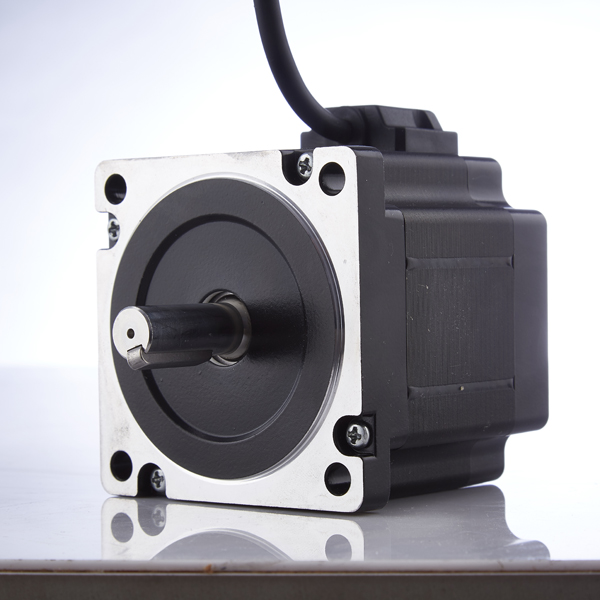
The rotor of a hybrid stepper motor is composed of two identical toothed iron cores, with the teeth of the two iron cores offset from each other and sandwiching an axially magnetized disc-shaped permanent magnet. The structure is shown in Figure 1.
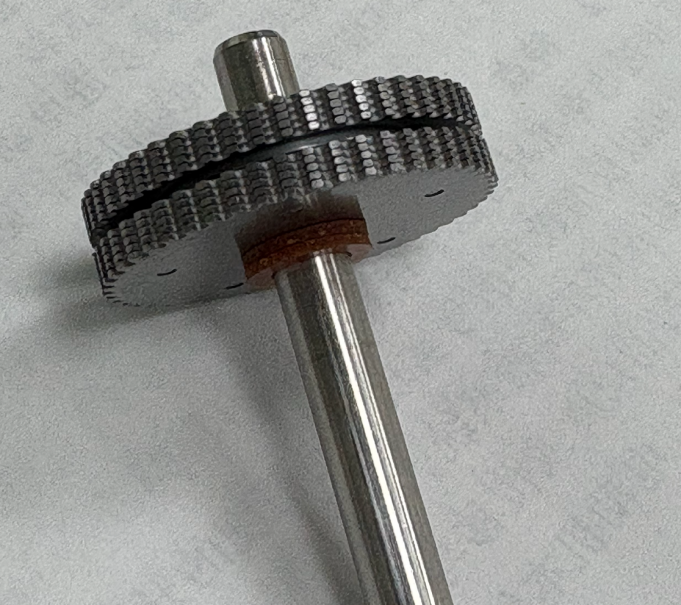
Figure 1: A typical stepper motor rotor
When the stator coil is not energized, the magnetic circuit of the permanent magnet passes through the N-pole - N-pole rotor core - rotor core side teeth - air gap - stator core side teeth - stator core - other stator core teeth - air gap - S-pole rotor core - S pole, as shown in Figure 2.
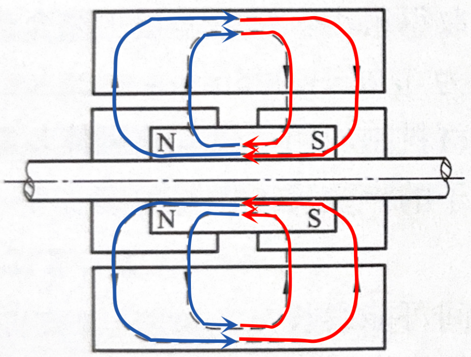
Figure 2 Permanent magnet magnetic circuit of hybrid stepper motor
(2) Armature magnetic circuit (stator)
The stator core of a hybrid stepper motor is a whole, with 8 pole shoes extending inward, teeth, and tooth pitch consistent with the rotor. Coils are wound around the 8 poles. For a typical 2-phase motor, the coils are distributed between the two phases, A/B A -/B -/A/B A -/B -.
If the rotor permanent magnet is not magnetized and the stator coil is single-phase electrified, the magnetic circuit starts from the two opposite N poles and enters the rotor core through the air gap, then flows into the two S stator poles through the air gap, and finally returns to the N stator pole through the stator core, as shown in Figure 3.
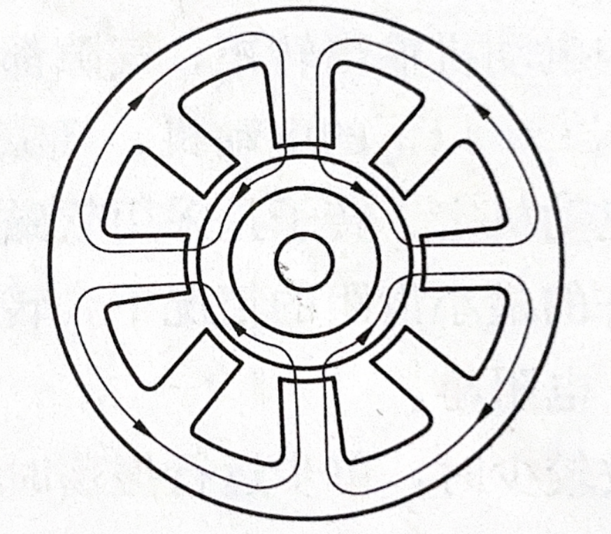
Figure 3 Magnetic circuit generated by excitation winding
(3) Synthetic magnetic circuit during operation
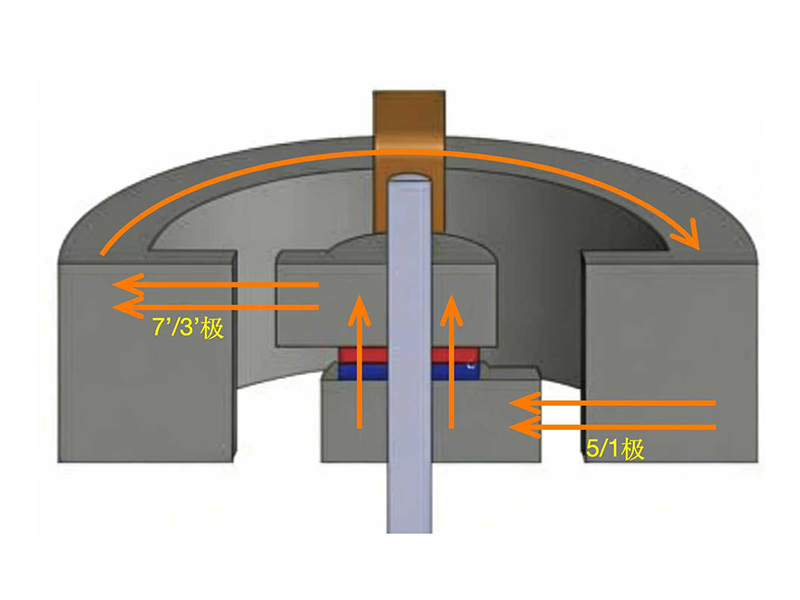
When a current is applied to the magnetized motor, the excitation magnetic field of the stator and the permanent magnetic field of the rotor interact, forming a new magnetic circuit. As shown in Figure 4, first observed from side (II), the magnetic field lines start from poles 1 and 5 (N pole) and enter the S pole rotor through the air gap between the aligned fixed rotor teeth. The magnetic field lines enter the S pole of the permanent magnet along the axial direction inside the rotor, and then exit from the N pole and enter the N pole rotor.
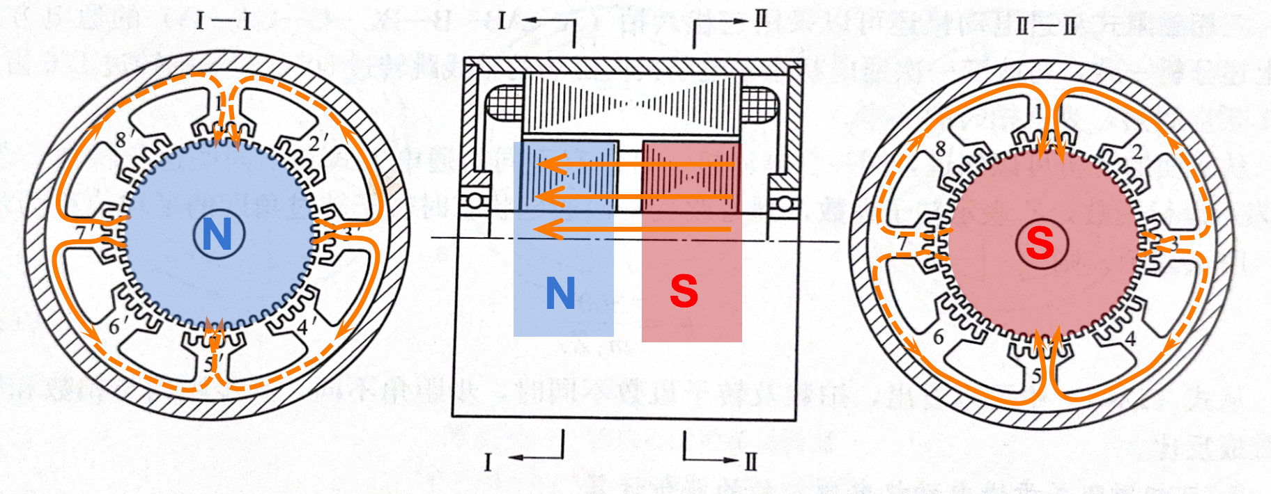
Figure 4 Synthetic magnetic circuit of hybrid stepper motor during operation
From the (I) side, the magnetic field lines of the N-pole rotor will converge towards the 7 'and 3' poles (S pole), enter the stator through the aligned air gap between the stator and rotor teeth, and then return to the 1 and 5 poles through the outer periphery of the stator core. Here, it can be seen that the two air gaps through which the magnetic circuit passes are the minimum magnetic resistance paths aligned with teeth -1 and 5 on the (II) side and 7 'and 3' on the (I) side. Figure 5 provides a clearer representation of the synthetic magnetic circuit during the operation of a hybrid stepper motor from a three-dimensional perspective.
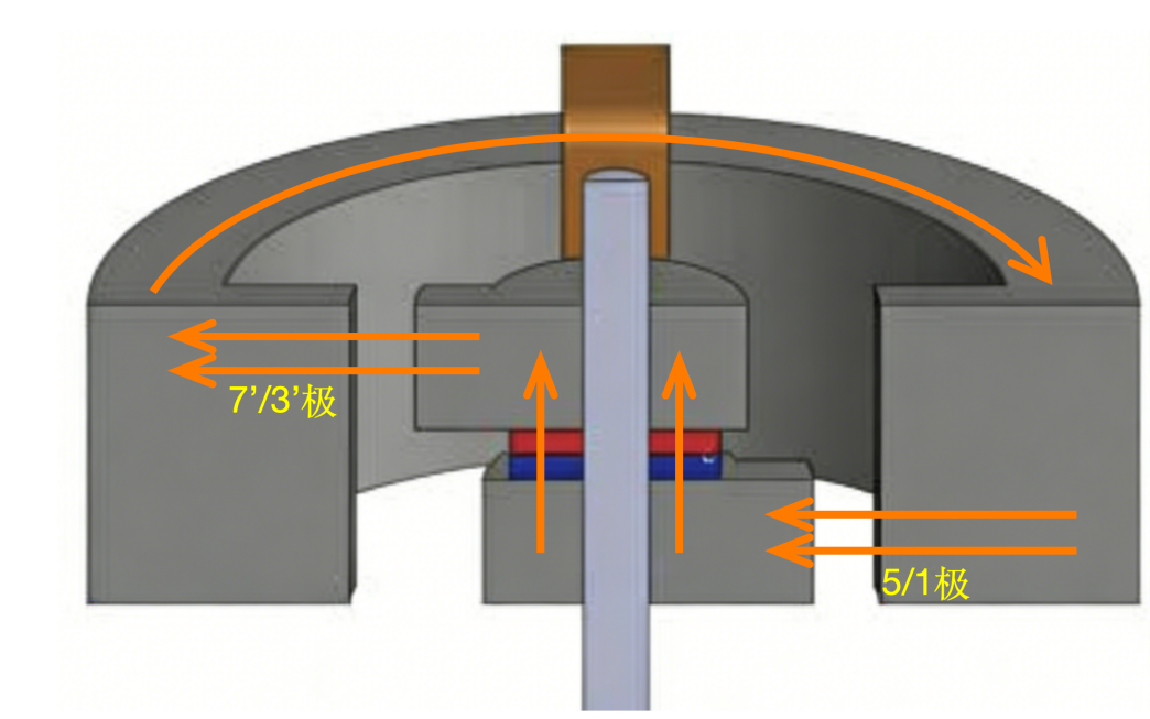
Figure 5: Part of the synthetic magnetic circuit during the operation of a hybrid stepper motor (from a perspective)