As a type of control motor, a stepper motor converts electrical pulse signals into angular displacement and is widely used in fields such as 3D printers, medical devices, and robotics. In previous articles, we have explained the operating principles of stepper motors extensively—mostly focusing on the motor itself. However, for a stepper motor, the importance of its driver is analogous to that of an operating system for a computer. To truly understand the core principles of stepper motor drivers, let’s begin with the fundamental operation mechanism of the stepper motor itself, gradually revealing the inherent contradictions faced in driver design and how modern driving technologies elegantly resolve them.
1. Why a Driver Is Needed
A stepper motor does not rotate using continuous current; instead, it requires its phase windings to be energized sequentially in a specific order.
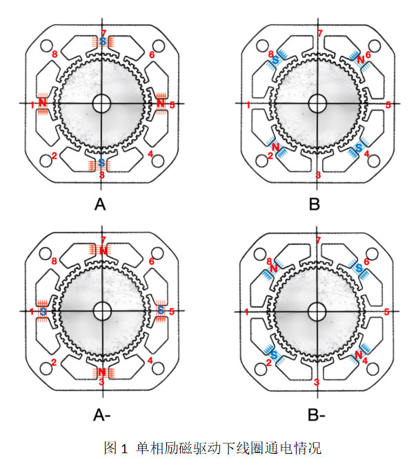
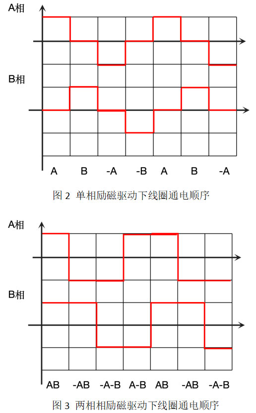
As shown in Figure 1, under single-phase excitation drive, phases A and B are energized sequentially in the order A → B → A̅ → B̅ → A. With each energization step, the rotor moves by one step angle. Repeating this cycle enables continuous rotation. The current waveforms for phases A and B are illustrated in Figure 2. In the case of two-phase excitation, both phases are energized simultaneously, as shown in Figure 3.
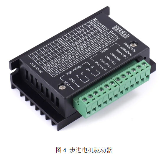
This operational method means that a stepper motor cannot be driven directly by a simple DC or AC power supply. Instead, it requires a dedicated "controller" to energize each phase winding in the correct sequence and timing. More critically, the duration of each pulse determines the motor speed—the higher the speed, the shorter the energization time per phase, often in the millisecond or even microsecond range. For example, with a 1.8° stepper motor driven at 500 pulses per second (pps), the rotational speed is calculated as: 60 × 500 × 1.8° / 360° = 150 rpm. In this case, each pulse lasts 2 ms, meaning each phase is energized for 2 ms. At 300 rpm, this duration drops to just 1 ms. Achieving precise on/off control within such short intervals is clearly impractical with manual operation or simple switches. This is precisely why stepper motor drivers exist: to deliver current to each phase winding on demand, on schedule, and in the correct sequence.
2. The Torque vs. Heat Dilemma
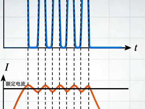
It is well known that the output torque of a stepper motor primarily comes from electromagnetic torque, which is directly proportional to the current flowing through the windings. Before magnetic saturation occurs, higher current yields greater torque. However, motor windings are made of fine copper wire. According to Joule’s law, heat generation Q = I²R (1). Thus, large currents cause rapid heat buildup, which can melt the insulation and ultimately burn out the motor.
This leads to the first contradiction: to achieve higher torque, we want as much current as possible; yet, to protect the motor, current must not exceed its rated value. But this is only the surface-level conflict—the real challenge lies ahead.
3. Inductance and Its “Procrastination”
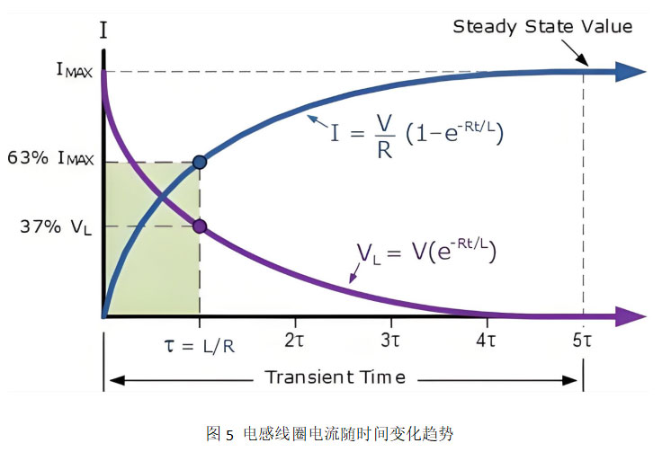
Coils possess not only resistance but also inductance. Inductance resists changes in current—when voltage is applied across a coil, the current does not instantly jump to its steady-state value U/R. Instead, it rises gradually according to the following equation:
I(t) = (U/R)(1 − e^(−t/(L/R))) (2)
Here, L/R is known as the time constant, which determines how quickly the current rises. Take a typical stepper motor as an example: phase resistance R = 9 Ω, phase inductance L = 18 mH. The time constant τ = L/R = 2 ms. This means it takes 2 ms for the current to reach 63% of its steady-state value, and about 6 ms (3τ) to reach 95%.
This characteristic poses a serious challenge at high motor speeds.
4. The Voltage Selection Dilemma
Suppose we apply a low voltage, say 9 V, to the winding. The steady-state current would be 9 V / 9 Ω = 1 A, which we assume is the motor’s rated current. At low speeds, the current has ample time to reach this steady state—no problem. But at higher speeds (e.g., 300 rpm), the energization time per phase may be only 1 ms. How much current can actually build up in 1 ms? Using the current formula, at t = 1 ms, I = 1 A × (1 − e^(−0.5)) ≈ 0.39 A—less than 40% of the rated current. Insufficient current means insufficient torque, causing the motor to lose steps or stall at high speeds.
Clearly, low voltage doesn’t work. What if we increase the voltage—say, to 24 V? At high speed, in 1 ms, the current would rise to (24/9) × (1 − e^(−0.5)) ≈ 1 A, barely meeting the requirement. However, at low speeds, with sufficient energization time, the steady-state current would reach 24/9 ≈ 2.6 A—far exceeding the rated value. Heat generation would then be roughly 7 times higher than rated conditions, leading to severe overheating or motor burnout. We find ourselves unable to simultaneously satisfy two requirements: “avoid excessive current at low speeds” and “build current quickly at high speeds.” This is the core contradiction in stepper motor driving: the conflict between voltage and speed.
5. From Compromise to Constant-Current Control
To resolve this contradiction, several approaches have been tried.
The earliest method was single-voltage constant-voltage driving. To improve high-speed performance, a high-voltage supply with a series resistor was used—allowing fast current rise at high speed while limiting current via the resistor at low speed to prevent overheating. However, this method is highly inefficient, as the series resistor dissipates significant power as heat.
Later, a high-low voltage driving scheme emerged: a high voltage is applied initially to rapidly build up current; once the current reaches the rated value, the system switches to a low voltage to maintain it. This approach partially balances fast response and steady-state safety, but its control logic is complex, and imprecise switching points still risk current overshoot.
These methods are essentially “open-loop” in current control—they cannot dynamically adjust based on actual current values, making precise and efficient operation difficult. The breakthrough came with the advent of chopper constant-current drive technology.
The core idea of chopper constant-current driving is simple: regardless of motor speed, the winding current is always maintained at a constant value—the rated current. Such drivers typically use a high supply voltage (e.g., 24 V or 48 V) but employ closed-loop control to limit current.
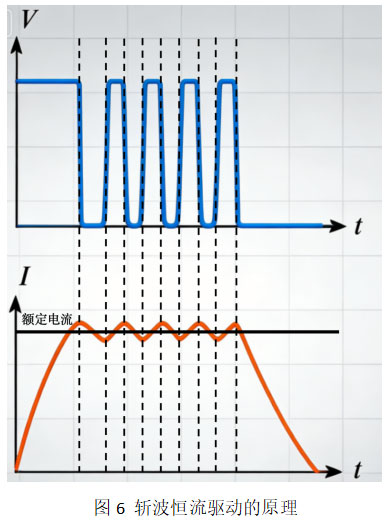
At the start of energization, when current is far below the setpoint, the driver fully turns on the switching transistor, applying the full high voltage directly to the coil. Current then rises extremely rapidly—reaching the setpoint (e.g., 1 A) in a very short time (e.g., 0.4 ms with 48 V for the earlier example). This solves the “insufficient current build-up at high speed” problem. Once the current hits the rated value, the driver immediately turns off the switch, halting the current rise. The current then begins to decay. As soon as the driver detects the current falling below the setpoint, it turns the switch back on, allowing current to rise again. Through this rapid on-off cycling—known as “chopping”—the current oscillates around the setpoint in a sawtooth waveform, with an average value equal to the target. This process can be visualized as using a high-pressure “pump” to quickly push current up, then a precision “valve” to prevent it from exceeding the safe limit. Regardless of speed, the driver continuously monitors actual current and adjusts the switch in real time to clamp the current at the desired level. How is this current measured? A small sense resistor is placed in the circuit, and the voltage across it is used to calculate the loop current. Most drivers allow users to set the rated current via DIP switches, which effectively adjust the reference for this sensing circuit.
Chopper constant-current control elegantly resolves the earlier contradictions: high voltage ensures rapid current establishment, enabling sufficient torque even at high frequencies; constant-current regulation prevents overcurrent and motor damage. Moreover, since the switching transistor operates primarily in either fully on (saturated) or fully off states, its power loss is far lower than in resistor-based limiting schemes, greatly improving efficiency.
Today, chopper constant-current driving has become the dominant method. It enables stepper motors to deliver stable torque across a wide speed range—from tens to thousands of RPM—making them indispensable foundational components in industrial automation.