Encoder is a sensor that provides feedback on position/velocity in motor control, and is the key to achieving closed-loop control of the motor. The basic principle is to convert location information into signals such as light, magnetism, capacitance, etc., and then convert these information signals into electrical signals. Encoders can be divided into signal types such as photoelectric encoders, magnetic encoders, capacitive encoders, inductive encoders, etc. Among them, photoelectric encoders and magnetic encoders are the most commonly used. The following mainly introduces the principles of these two encoders.
1、 Photoelectric encoder
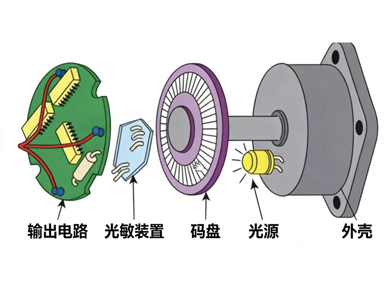
The principle of a photoelectric encoder is to use a light and dark grating to block the light source, and generate high and low levels on the photoelectric sensor on the other side of the grating, thereby converting position information into electrical signals (Figure 1).
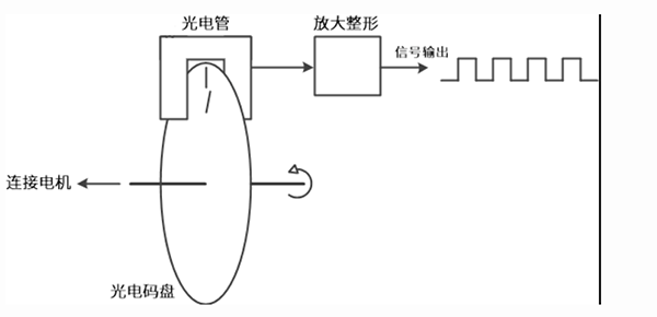
Figure 1 Structure of photoelectric encoder
1. Position/angle. If there are n gaps on the grating disk, then every 360 °/n rotation of the disk will emit a high-level signal, and the accuracy of this encoder is 360 °/n. By counting the number of signals, we can know how many degrees have been rotated, which is the displacement signal. With position/displacement information, dividing by time yields velocity information.
2. Direction. Adding another set of gratings with a phase difference of 90 ° (electrical angle) can achieve this goal (two gratings can be integrated on a disk, as shown in Figure 2). It is not difficult to observe that when rotating clockwise (Figure 3), the rising edge of the A-phase signal (low high level, or dark bright) always corresponds to the high-level state of the B-phase (bright); Conversely, when rotating counterclockwise (Figure 4), the falling edge of the A-phase signal always corresponds to the high-level state (bright) of the B-phase. This way, the direction of rotation can be determined.
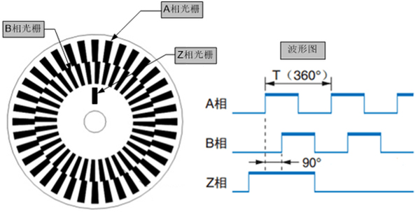
Figure 2 Grating structure of incremental photoelectric encoder encoder encoder disc
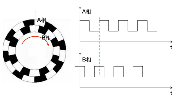
When rotating clockwise in Figure 3, the rising edge of the A-phase signal always corresponds to the high level of the B-phase
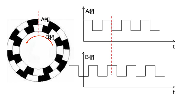
When rotating counterclockwise in Figure 4, the falling edge of the A-phase signal always corresponds to the high level of the B-phase
Based on the above principles, we can obtain an incremental photoelectric encoder. The reason why it is called "incremental" is because we found that the AB phase grating structure shown in Figure 2 is uniform. When it rotates to any position, we can only know how many angles it has rotated by the number of output signals, but we cannot know the specific position. If this encoder suddenly loses power during operation, and after recovery, the previously run signal is lost, then the position information is lost, and to continue measuring, it must return to "zero" and run again. Incremental encoders are suitable for measuring speed, while measuring position depends on the zero point.
What if we want to determine position information without relying on zeros, we need to use an absolute value encoder. The principle is also very simple, if we make the "shape" (or encoding) of each subdivision interval of the entire circumference different. The absolute value encoder shown in Figure 5 has a concentric circle structure, where each concentric circle is called a code track. The disk is then divided into N equal parts, and 360 °/N is the accuracy of the absolute value encoder.
Here, N is usually 2 ^ k, and k is the number of code tracks (actually binary).
For example, as shown in Figure 5, a code wheel with 3 tracks can be divided into up to 8 equal parts, with an accuracy of 45 °. The three code lines in each sector interval are the three bits of the binary number (□□□), and this unique code corresponds to this sector interval.
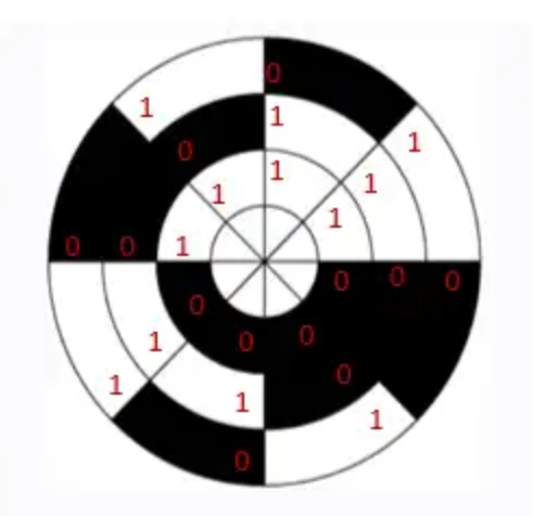
Figure 5 Absolute value photoelectric encoder encoder encoder disc
If we want to improve accuracy, we need to increase the number of code channels, with an accuracy of 360 °/(2k). If the number of code tracks is increased to 8, the accuracy can reach 1.4 °. Of course, the equal score does not necessarily have to be equal to 2k. As long as it is less than this number, it is sufficient to ensure that each interval has a unique encoding (for example, 8-bit encoding can divide the disk into 200 equal parts with an accuracy of 1.8 °)
2、 Magnetic encoder
Magnetic encoders can be divided into Hall type and magnetoresistance type based on two types of electromagnetic effects.
The Hall type magnetic encoder utilizes the Hall effect, where a current carrying conductor in a magnetic field forms a voltage perpendicular to the direction of the magnetic field and current.
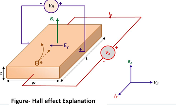
Figure 6 Hall Effect Principle (from Baidu Baike)
According to this principle, as long as a radially magnetized magnet is attached to the rotating shaft of the motor, a periodically changing magnetic field can be generated, and nearby Hall elements can output changing voltage signals, thereby outputting position information. The structure of the Hall type magnetic encoder is very similar to the photoelectric encoder shown in Figure 1, except that the grating is replaced with a magnet and the photoelectric sensor is replaced with a Hall element. Similarly, to measure the direction of rotation, a Hall element needs to be placed at a position with a phase difference of 90 ° (electrical angle), following the same principle as described in Figures 3 and 4.
The magneto resistive encoder utilizes the magneto resistive effect, which means that the resistance of certain materials will undergo regular changes in a magnetic field (related to the influence of Lorentz force on charge carriers in the magnetic field). Based on this characteristic, periodic electrical signals can also be output, and position information can be input by counting the number of electrical signals. The basic structure and principle are similar to Hall encoders.
Optical encoders and magnetic encoders are the most commonly used types of encoders, each with its own advantages. The photoelectric encoder has high accuracy and resolution, and corresponding speed, but it has high environmental requirements and low tolerance to dust, oil, and vibration. It is generally used in high-precision machine tool equipment. Magnetic encoders can withstand harsh environments such as dirt and dirt, and have relatively low costs. However, their accuracy is lower than that of optical encoders, and they are easily affected by external magnetic fields.
Original statement: This article is the original content of Jindi Electric. Please indicate the source when reprinting. Thank you!