Stepper motors are mainly divided into three categories: Permanent Magnet (PM), Variable Reluctance (VR), and Hybrid (HB). The Hybrid type is a hybrid or combination of the former two. Therefore, from a principle perspective, the Permanent Magnet and Variable Reluctance types can be considered the most fundamental. Our previous articles have provided detailed introductions to Hybrid and Permanent Magnet stepper motors. This article will introduce the Variable Reluctance stepper motor, also known as the VR-type stepper motor.
I. Structure of VR-Type Stepper Motors
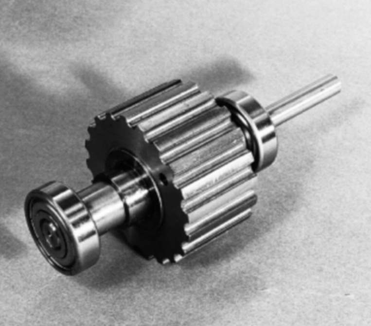
The stator and rotor of a VR-type stepper motor are both made of soft magnetic materials, requiring no permanent magnets. Structurally, the rotor has a uniform toothed structure (as shown in the figure), and the stator has many pairs of excitation windings called poles. Each pole also has a toothed structure identical to the rotor's, and the teeth on adjacent poles are intentionally offset from the rotor teeth by a specific angle. Hybrid stepper motors have effectively inherited this structure, and both share the same principle for generating step angles.
Figure 1: Rotor Structure of a VR-Type Stepper Motor
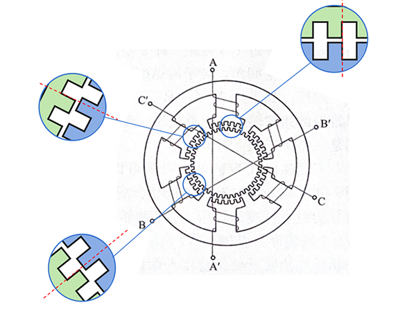
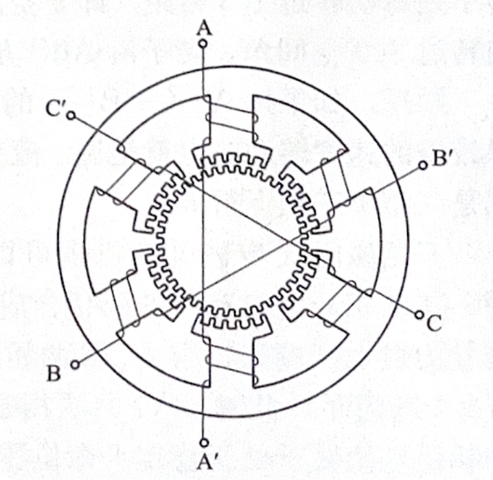
Figure 2 shows a schematic diagram of a typical three-phase VR stepper motor structure. The stator has three pairs of magnetic poles, with one phase winding wound around each pair. The tooth pitch on the rotor core and stator pole shoes is equal. In the figure, the rotor core has 40 teeth, resulting in a spatial angle of 9° per tooth.
Figure 2: Schematic Diagram of a Typical 3-Phase VR-Type Stepper Motor Structure
It can be seen that when the rotor teeth are aligned with the teeth of one phase (A), they are always offset from the teeth of the other two phases (B/C) (as shown in the figure). This offset angle is 1/3 of a tooth pitch (3°) respectively. The purpose of this design will be explained in the step angle principle section below.
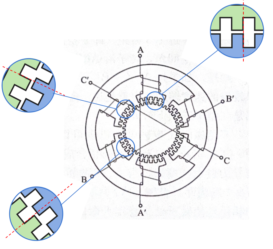
Figure 3: Relative Relationship Between Three-Phase Stator Teeth and Rotor Teeth
II. Principle of VR-Type Stepper Motors
As a Variable Reluctance stepper motor, its operating principle utilizes the concept that a "magnetic field system always tends to achieve the state of minimum magnetic reluctance" to drive rotor movement. When the magnetic reluctance of the system is minimized, the overall energy is lowest, and the system always tends towards the lowest energy state, similar to the principle of "water flowing downhill."
Imagine a magnet attracting an iron nail through the air; the principle of a VR stepper motor is analogous to this.
Returning to the stator-rotor structure of the VR stepper motor, it's clear that when stator and rotor teeth are aligned, the air gap is smallest, and magnetic reluctance is minimized. Conversely, when teeth face slots, the air gap is largest, and magnetic reluctance is maximized.
Assuming initially, phase A is energized. Then, obviously, the teeth of the stator poles of phase A will correspond one-to-one with the rotor teeth, achieving the state of minimum reluctance (as shown in Figure 3).
Then, we switch to energizing phase B. At this point, since the teeth of the stator poles of phase B and the rotor teeth are offset by 1/3 of a tooth pitch, it is clearly not the state of minimum reluctance. Therefore, attracted by the stator poles, the rotor will rotate counterclockwise by 1/3 of a tooth pitch to align with the stator teeth of phase B.
Following the same logic, if we then switch to energizing phase C, the stator teeth of phase C and the rotor teeth are still offset by 1/3 of a tooth pitch, so the rotor will continue to rotate counterclockwise by another 1/3 of a tooth pitch.
By repeating this cycle sequentially energizing phases in the order A-B-C-A, the rotor rotates continuously (counterclockwise). The step angle is the angle corresponding to 1/3 of a tooth pitch, i.e., 3°. Conversely, energizing in the order A-C-B-A causes the motor to rotate clockwise.
Extending from the three-phase VR stepper motor, the principle is exactly the same for four-phase, five-phase, and VR stepper motors with more phases. The only difference is that the teeth on adjacent stator poles need to be offset by an angle of 1/p of a tooth, where p is the number of motor phases. This offset angle is the step angle. Therefore, for a VR stepper motor, the step angle θ = (1/p) * (360°/Z), which is 360°/(pZ), where p is the number of phases and Z is the number of rotor teeth.
III. Control of VR-Type Stepper Motors
The previous section mentioned that when the three phases are energized individually in sequence, the motor rotates with a step angle of θ. The energization sequence is A-B-C-A or the reverse.
It is also possible to energize two phases simultaneously. In this case, the direction of the combined magnetic field from the two phases lies exactly along the bisector of the angle between the magnetic field directions produced by energizing each phase individually. For example, energizing phases A and B simultaneously produces a combined magnetic field direction that causes the rotor teeth to be offset by 1/6 of a tooth pitch from both phase A teeth and phase B teeth. Subsequently, changing the energization sequence in the pattern AB-BC-CA-AB will still cause the rotor to rotate with a step angle of θ.
If we alternate between single-phase and two-phase energization, following the sequence A-AB-B-BC-C-CA-A (i.e., 6 steps per cycle), it's clear that each step rotates the rotor by 1/6 of a tooth pitch. Thus, the rotor will rotate with a step length of θ/2. This is the same principle as half-stepping in hybrid stepper motors.
Furthermore, if we not only control the on/off state of each phase but also control the magnitude of the phase currents, we can more precisely control the direction of the combined magnetic field, resulting in even smaller step lengths. This is the principle of microstepping (subdivision driving).
IV. Characteristics of VR-Type Stepper Motors
(1) Similar to hybrid stepper motors (or rather, hybrid stepper motors are similar to VR types), VR stepper motors have a very small air gap, primarily to increase torque. However, due to relying solely on attractive forces, compared to hybrid stepper motors, VR stepper motors have significantly lower torque.
(2) The rotor of a VR stepper motor is made of soft magnetic material, allowing for a relatively large number of teeth. Combined with the number of stator phases, the step angle can be made very small, offering much better precision compared to PM motors.
(3) Since VR stepper motors do not use permanent magnets, their manufacturing cost is lower than that of hybrid stepper motors. However, due to the small air gap requiring precision machining for both stator and rotor, their cost is not necessarily lower than that of PM stepper motors.
(4) As VR stepper motors have no permanent magnets, they naturally have no detent torque when power is off.
In summary, the VR-type stepper motor is a type of motor driven purely by magnetic reluctance, with a relatively simple structure and an easily understandable driving principle. The principles of the VR stepper motor determine its unique structure and characteristics, leading to its application in many specific scenarios.