Stepper motors are mainly classified into three types: Permanent Magnet (PM), Variable Reluctance (VR), and Hybrid (HB). The torque of a PM stepper motor originates from the interaction between the stator excitation magnetic field and the rotor permanent magnetic field, known as electromagnetic torque. VR stepper motors contain no permanent magnets; their torque arises from the tendency of the salient-pole structure to minimize magnetic reluctance, referred to as reluctance torque. Hybrid stepper motors combine the characteristics of PM and VR types, so their torque results from the combined action of electromagnetic torque and reluctance torque. This paper details the torque sources of hybrid stepper motors.
1. Permanent Magnet Torque
Permanent magnet torque provides the dominant torque in hybrid stepper motors, derived from the interaction between the magnetic field generated by excitation coils and the rotor permanent magnetic field.
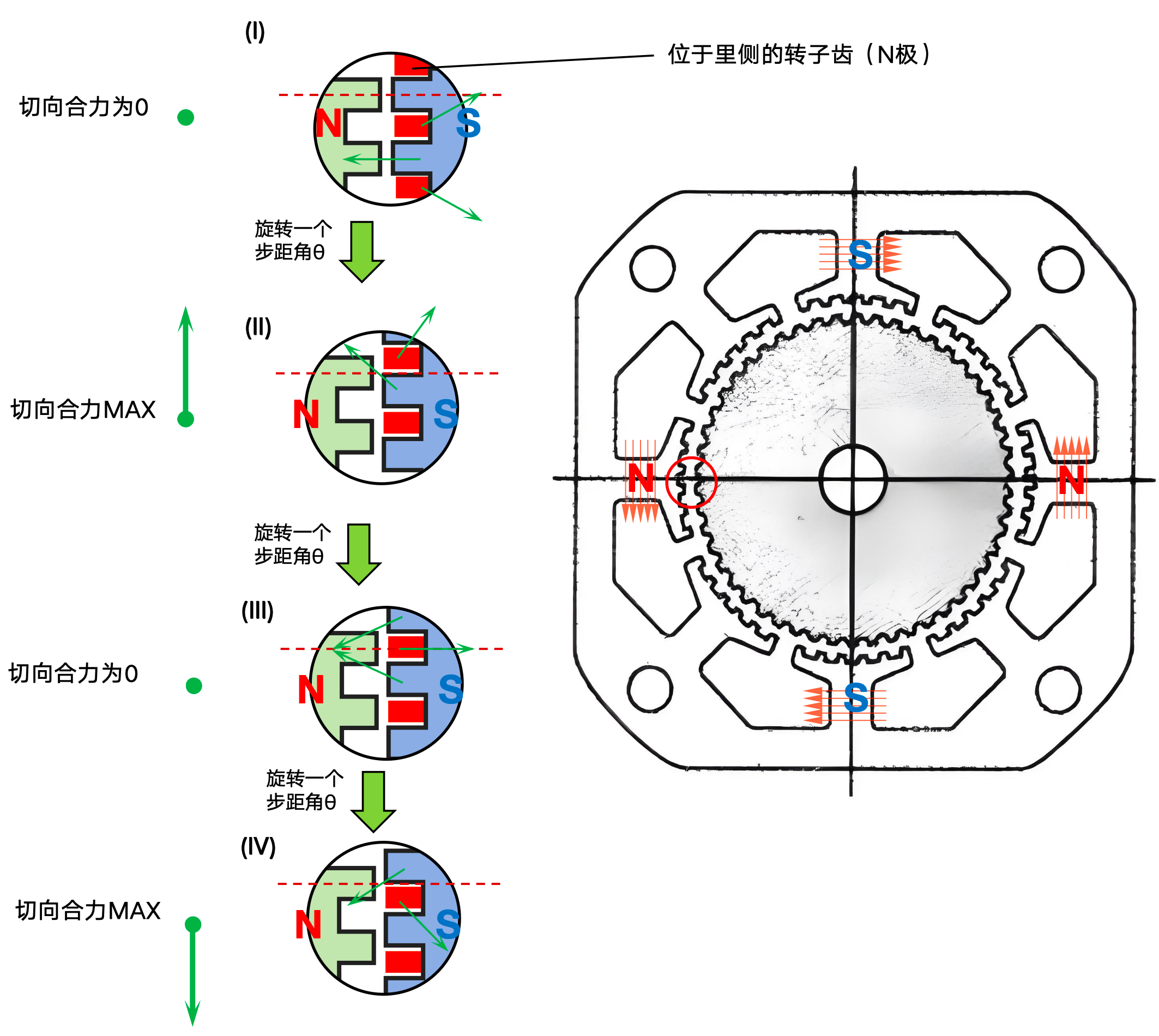
Figure 1 Force analysis of the rotor at different positions with single-phase energization
As shown in Figure 1, when one phase of the stepper motor is energized, the left and right stator poles are N-poles, and the upper and lower poles are S-poles. The outer side of the rotor is S-pole, and the inner side is N-pole. Taking the leftmost stator and rotor teeth for analysis, Position (I) is a stable equilibrium position where the N-pole teeth of the stator align with the S-pole (outer) teeth of the rotor and misalign with the N-pole (inner) teeth. Force analysis shows that the electromagnetic forces exerted on the rotor by each stator tooth are symmetric, canceling each other tangentially with a resultant force of zero.
Rotating the rotor clockwise generates a counter-torque that pulls the rotor back toward Position (I). When rotated by one step angle θ to the half-aligned Position (II), the tangential resultant force reaches its maximum. Further rotation reduces the tangential force gradually; at 2θ rotation to the fully misaligned Position (III), the tangential resultant force becomes zero.
Continuing rotation causes the resultant force on the rotor to become clockwise and increase, peaking at 3θ rotation (Position IV). Further rotation reduces the torque to zero, returning to Position (I), completing one full torque cycle.
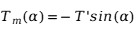
The analysis shows that the electromagnetic torque varies with a period of four step angles, corresponding to one full electrical cycle. Defining clockwise rotation as positive, torque is negative for 0–2θ and positive for 2θ–4θ. Electromagnetic torque can be expressed as:
 |
(1) |
where Tm = electromagnetic torque, T′ = maximum electromagnetic torque, α = rotational angle (electrical angle), and one step angle corresponds to π/2 electrical radians. The curve of Tm is shown in Figure 2.
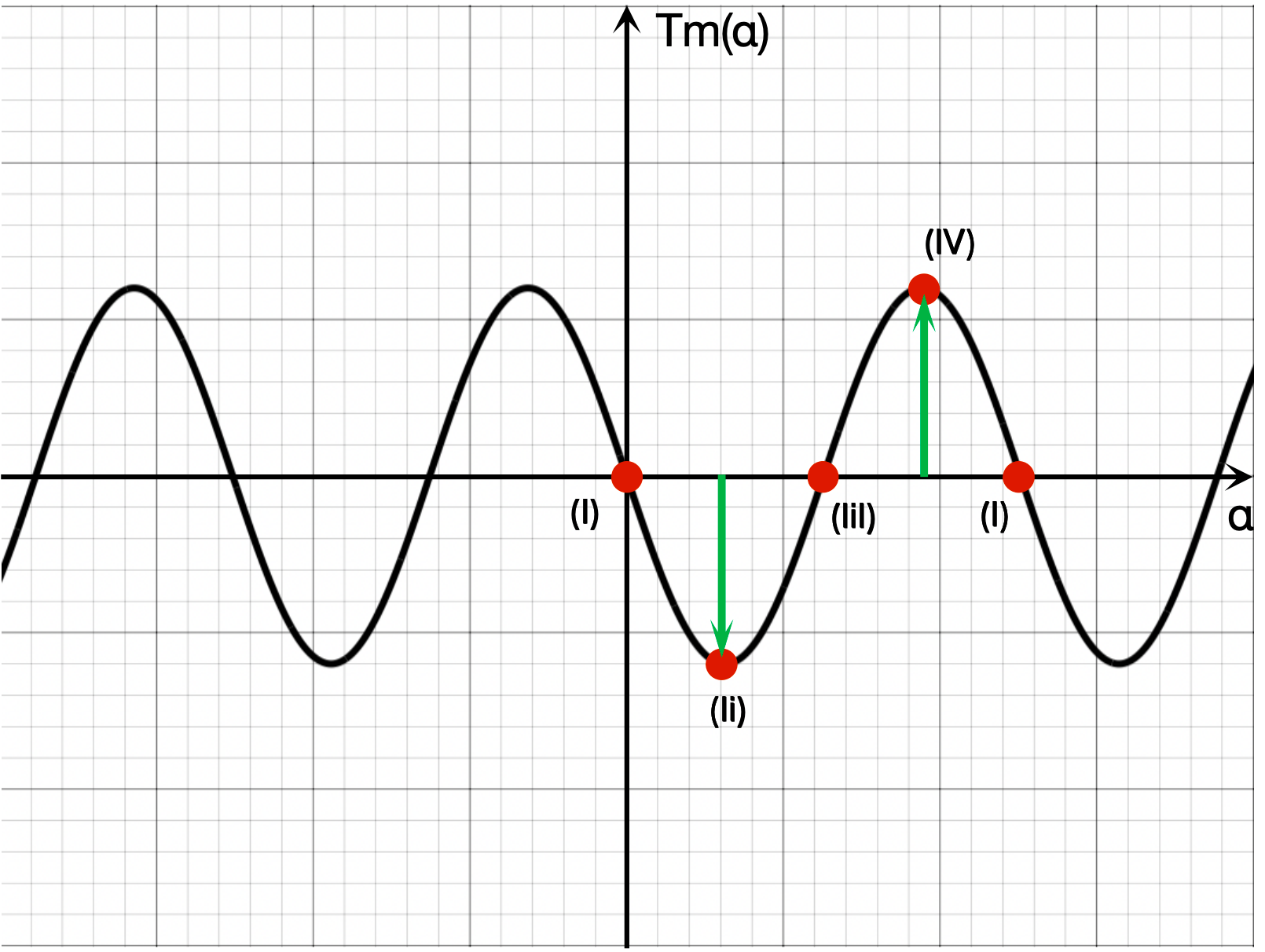
Figure 2 Electromagnetic torque as a function of rotational angle
2. Reluctance Torque
Reluctance torque is produced solely by the salient-pole structure. To study reluctance torque, electromagnetic torque must be excluded by using an unmagnetized rotor. Periodic changes in air-gap reluctance between stator and rotor teeth generate periodic reluctance torque. For salient-pole structures, reluctance torque follows a trigonometric pattern with half the period of electromagnetic torque, understandable via a simple two-pole salient model.
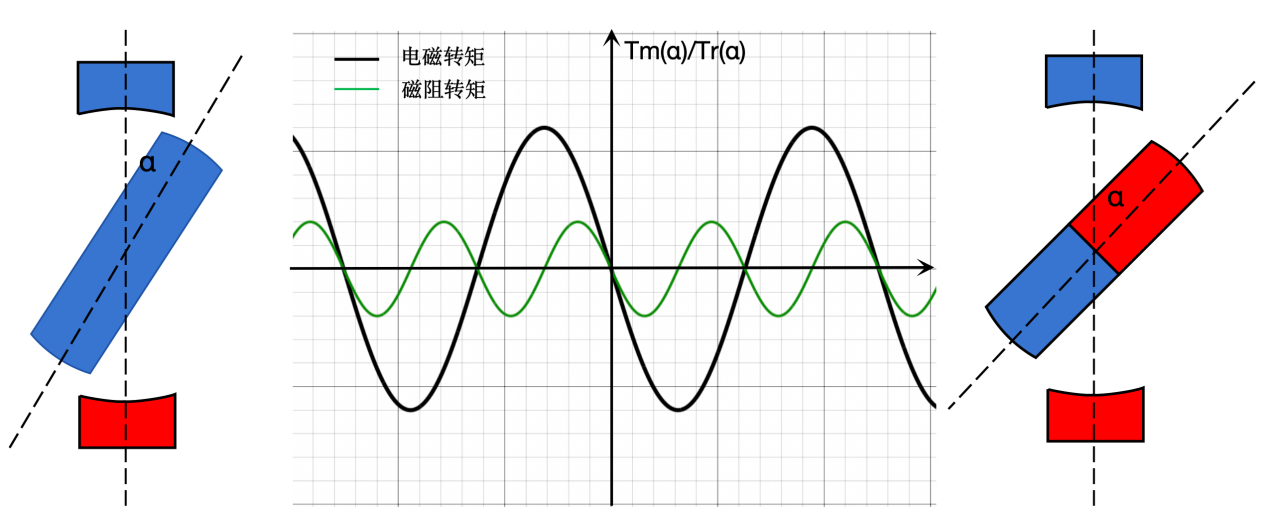
Figure 3 Electromagnetic and reluctance torque vs. rotational angle for a two-pole salient structure
As shown in Figure 3, the stator has two poles and the rotor two salient poles. A permanent-magnet rotor produces one torque cycle per revolution; a soft-magnetic rotor produces two cycles of reluctance torque per revolution.
In typical hybrid stepper motors, aligned stator–rotor teeth of like polarity form an unstable equilibrium point; displacement generates torque in the direction of motion. Reluctance torque can be expressed as:
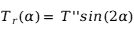 |
(2) |
where Tr = reluctance torque, T′′ = maximum reluctance torque, α = rotational angle (electrical angle), one step angle = π/2 electrical radians. The waveforms of electromagnetic torque, reluctance torque, and their combination are shown in Figure 4.
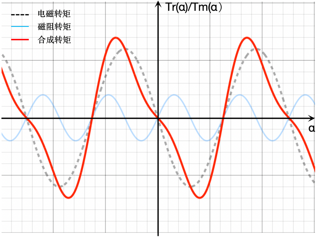
Figure 4 Reluctance and electromagnetic torque vs. deflection angle
3. Cogging Torque
In addition to electromagnetic and reluctance torque, hybrid stepper motors exhibit cogging torque, also called detent torque. Rotating the rotor with stator coils de-energized produces periodic detent forces, arising from the tendency of the permanent-magnet rotor and salient structure to minimize magnetic reluctance. Cogging torque in hybrid stepper motors contains only 4k-order harmonics[1]; high-order components are negligible, so only the 4th harmonic is considered. Cogging torque can be expressed as:
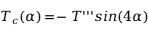 |
(3) |
where Tc = cogging torque, T′′′ = maximum cogging torque, α = rotational angle (electrical angle), one step angle = π/2 electrical radians.
With cogging torque included, the resultant motor torque vs. deflection angle is shown in Figure 5.
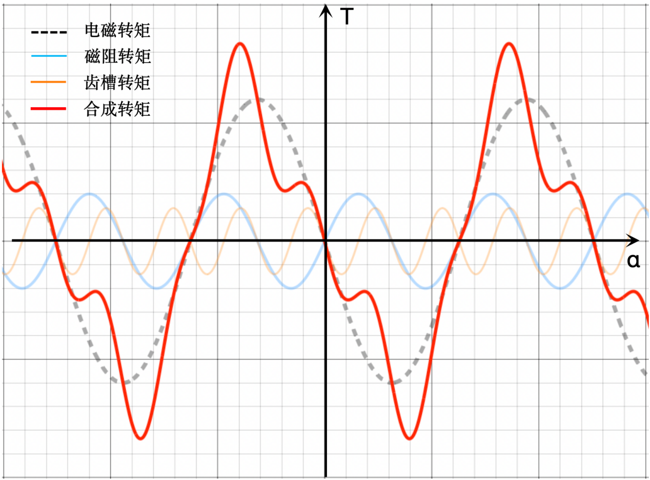
Figure 5 Resultant torque of electromagnetic, reluctance, and cogging torque vs. deflection angle
The magnitudes of electromagnetic, reluctance, and cogging torque are unknown in the above analysis, so Figure 5 is schematic. Measurements were taken using a torque meter to determine their actual magnitudes.
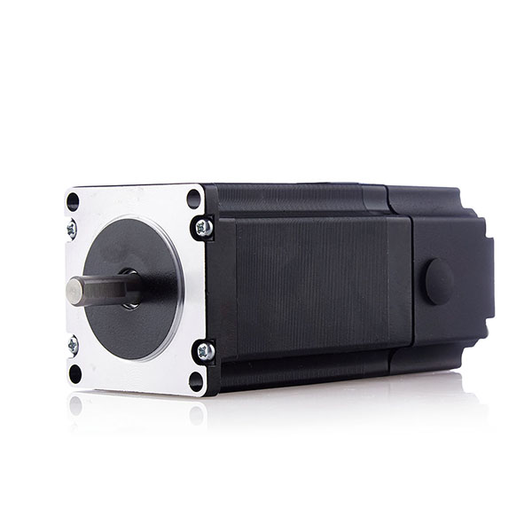
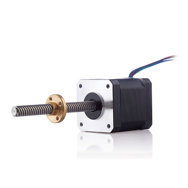
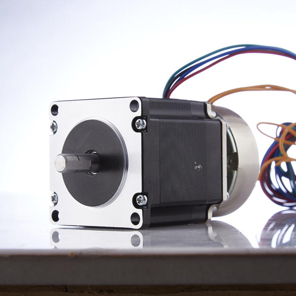
The test prototype is a Type HD42 hybrid stepper motor manufactured by Golden Motor. Test conditions and results are as follows:
|
Test Conditions |
Torque / cNm |
Electromagnetic Torque |
2 A, single-phase energized |
250 |
Reluctance Torque |
2 A, single-phase energized, unmagnetized rotor |
9 |
Cogging Torque |
De-energized |
17 |
Reluctance and cogging torque are one order of magnitude smaller than electromagnetic torque, which dominates motor operation.
Cogging torque is time-invariant during operation; its work is given by:
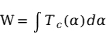 |
(4) |
As a periodic function, the integral of cogging torque over a full cycle is zero. Thus, cogging torque does no net work during operation and only distorts the resultant torque waveform.
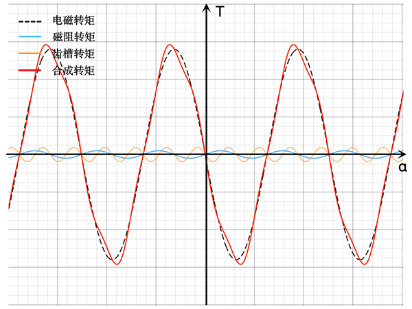
Using measured data, Figure 5 is replotted as Figure 6, showing the actual combined torque. Although reluctance and cogging torque have small amplitudes, they distort the ideal sinusoidal waveform.
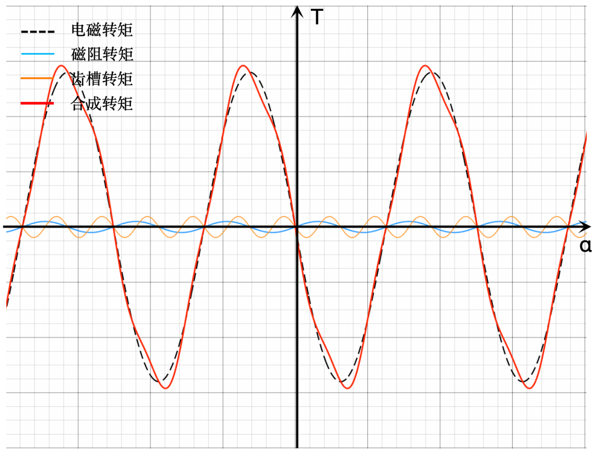
Figure 6 Actual resultant torque of electromagnetic, reluctance, and cogging torque vs. deflection angle
Conclusions:
(1) Electromagnetic torque period = 4 step angles (4θ), reluctance torque = 2θ, cogging torque = θ.
(2) Torque of hybrid stepper motors is the combination of electromagnetic and reluctance torque, with electromagnetic torque dominant. Cogging torque is a conservative force with zero average work.
(3) In practical hybrid stepper motors, electromagnetic torque magnitude is one order of magnitude larger than reluctance and cogging torque (a form of reluctance torque).