Taking a hybrid stepper motor with a step angle of 1.8 ° as an example. 50 teeth rotor; The stator has 8 poles, with 6 teeth per pole, for a total of 48 teeth.
Firstly, let's take a look at the static structure of the stator and rotor. The rotor is evenly arranged with 50 teeth. The stator has 48 teeth divided into 8 poles, with 6 teeth per pole. The tooth pitch on each pole is consistent with that of the rotor and can correspond one-to-one. The arrangement of stator teeth can be understood as follows: Cut off 2 complete teeth (i.e. 2 tooth tips and 2 tooth slots) from the 50 teeth that originally corresponded one-to-one with the rotor, and divide them into 8 poles evenly arranged on the circumference in sequence.
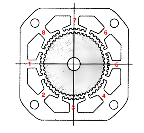
Figure 1 Schematic diagram of stator structure of stepper motor
Mark the 8 poles of the stator counterclockwise as 1-8 # in sequence. Mark the first tooth of the first pole as stator tooth 1 and mark it counterclockwise in sequence. The rotor teeth corresponding to stator tooth 1 are labeled as rotor tooth 1, and are marked counterclockwise in sequence. Align the first pole with the rotor teeth exactly, as shown in Figure 2.
Align the first pole stator and rotor one by one.
Due to the existence of the pole gap, the second pole stator teeth "lead" the rotor teeth by 1/4 of a tooth, which is called "semi alignment". (Refer to the position relationship of the 7th tooth of the stator/rotor)
The same third pole "leading" rotor has an additional 1/4 tooth, which is 1/2 tooth, completely offset. You can refer to the position relationship of the 13th fixed/rotor tooth. The teeth of the fourth pole are "leading" by 3/4 of the rotor teeth, semi aligned; The fifth pole "leads" by a complete tooth, so the stator and rotor teeth are perfectly aligned again.
The following steps 6, 7, and 8 repeat the above process, and finally return to the first pole. Throughout the entire process, the stator and rotor are two teeth apart.
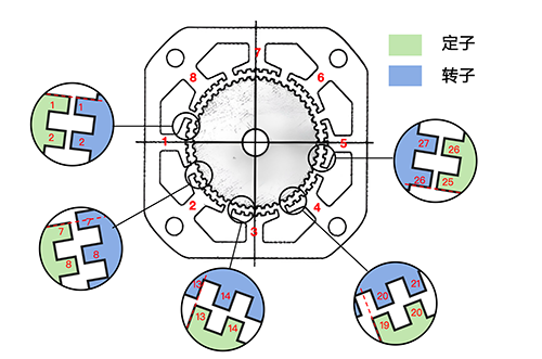
Figure 2 Corresponding relationship between the structure of the rotor and stator teeth of a static stepper motor
Next, let's take a look at how the stepper motor rotates.
Two sets of coils, called A phase and B phase, will be wound around the 8 pole claws. Refer to Figure 2 for the winding method. Among them, poles 1, 3, 5, and 7 are one phase (phase A), corresponding to one line, while poles 2, 4, 6, and 8 are another phase (phase B), corresponding to another line, leading out a total of four wire ends. Figure 3 shows the winding direction of each winding, with arrows representing the winding direction of the wire harness outside the paper plane.
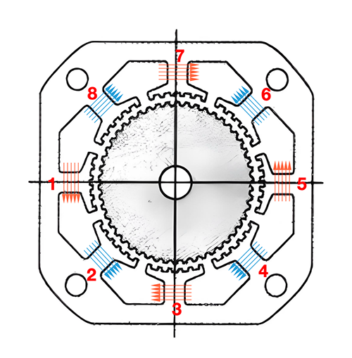
Figure 3 Winding direction of winding
If the magnetic pole direction generated by the current flowing through the AB two-phase wheel is shown in Figure 4.

Figure 4 Different phase current directions and magnetic pole directions
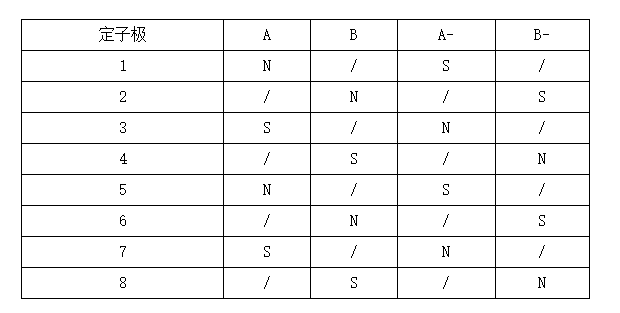
Use a table to identify as:
Next, we will analyze how the rotor rotates.
Assuming that the fixed rotor is initially in the position shown in Figure 1, according to A>; B> A-> B-> Power on in sequence A.
So in the first step, when A is electrified, the N-pole teeth of stator 1 and 5 align with the S-pole teeth of the rotor, and the S-pole teeth of stator 3 and 7 align with the rotor slot (i.e. the N-pole teeth of the rotor inside the paper), which is exactly in the equilibrium position. Refer to Figure 5.
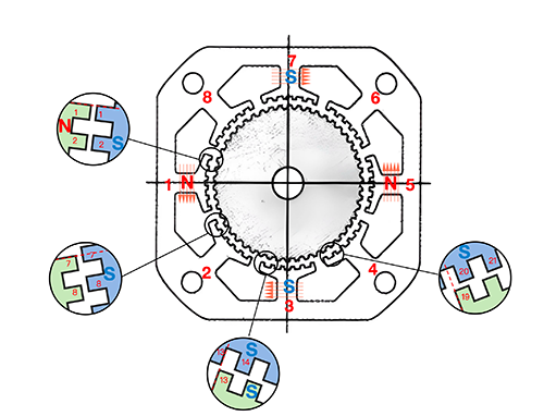
Figure 5: When A is initially connected to a forward current (A), the rotor is in a balanced state
In the second step, B is electrified, as shown in Figure 6. The second and sixth stator poles generate counterclockwise attraction to the rotor (outside the paper surface), while the fourth and eighth stator poles generate counterclockwise repulsion to the rotor (outside the paper surface), causing the rotor to start rotating counterclockwise. The above analysis of the force on the outer rotor of the paper surface is actually the same for the force analysis on the rotor measured inside the paper surface. Due to the complete misalignment of the teeth of the inner and outer rotors, the magnetic poles are opposite, and the position of the outer tooth slot is the position of the inner tooth top. At this time, the second and sixth stator poles generate a counterclockwise repulsive force on the inner rotor of the paper surface, while the fourth and eighth stator poles generate a counterclockwise attractive force on the inner rotor. Overall, in this step, the torque direction generated by the four stator poles on the inner and outer rotors is counterclockwise.
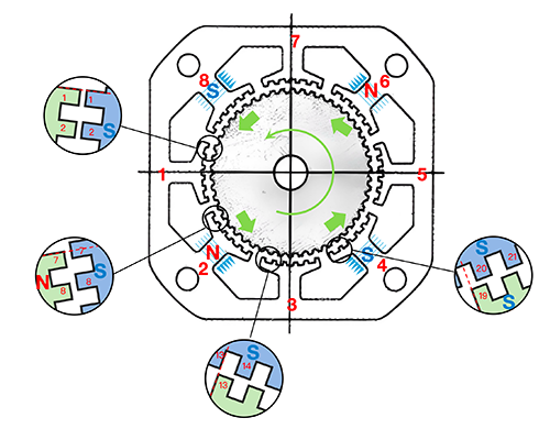
Figure 6 Force analysis of rotor after positive electrification of phase B
Obviously, the step size for one rotation is 1/4 of a tooth, and a circumference of 360 ° is divided into 50 teeth. Each step size for 1/4 of a tooth means that a total of 200 steps are required for one rotation, with each step being 1.8 °. That's why the full step size of an 8-pole two-phase 50 tooth stepper motor is 1.8 °. After the second step of rotation, the rotor will rotate to a new equilibrium position as shown in Figure 7.
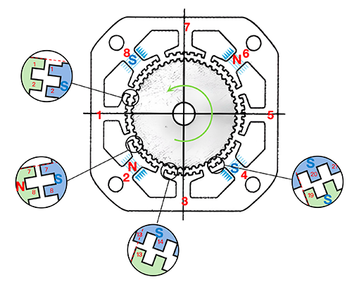
Figure 7 Balance position of phase B after forward electrification
Step three, A is connected to a reverse current (A -), and the force on the rotor is shown in Figure 8. The first and fifth stator poles generate counterclockwise repulsive (external) and attractive (internal) forces on the rotor, while the third and seventh stator poles generate counterclockwise attractive (external) and repulsive (internal) forces on the rotor. In short, the torque direction applied to the rotor is still counterclockwise, which allows the rotor to continue rotating 1.8 ° to the next position (Figure 9)

Figure 8 Force distribution of rotor after reverse electrification of phase A
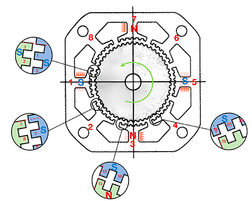
Figure 9 Balance position of phase B reverse electrification
The fourth step B is to apply a reverse current (B -), which still generates a counterclockwise torque on the rotor. If this continues, the rotor will gradually rotate step by step.
In the case where the first step remains unchanged, if the opposite current (B -) is applied in the second step B, the initial torque applied to the rotor will become clockwise. According to A>; B-> A-> B> If A is powered on in sequence, the rotor will continue to rotate clockwise.
In the above rotation mode, the A and B phase wheels are electrified, and this driving mode is called "single-phase excitation full step drive". By adjusting the sequence and rhythm of electrification, the step size and torque can be changed, such as "two-phase excitation full step drive", "hybrid excitation half step drive", etc.
Above, we have disassembled the structure and rotation mode of stepper motors in great detail, and established a very intuitive model. Based on this model, we will continue to explain other important concepts of stepper motors in the future.
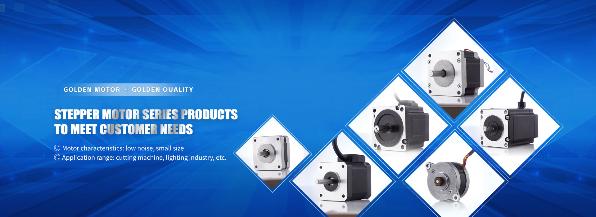
Jindi Motor has been deeply involved in the field of stepper motors for more than ten years. Based on a profound understanding of the structural principles of stepper motors, Jindi continues to provide customers with high-quality services and constantly innovate. In the following series of articles, Jin will take you to continue understanding stepper motors.
Dongguan Jindi Motor Co., Ltd
Golden Motor Golden Quality
http://www.goldenmotor.cn