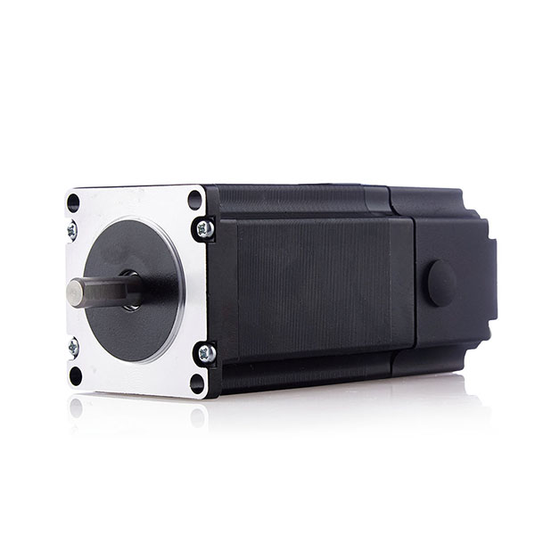
This small motor, which looks rather ordinary—similar to the tiny DC motor found in those counterfeit Audi Twin Drill four-wheel-drive toy cars from childhood—is actually a PM (Permanent Magnet) stepper motor. Despite its compact size, it features a simple yet ingeniously designed structure. This article will help you understand how PM stepper motors work!
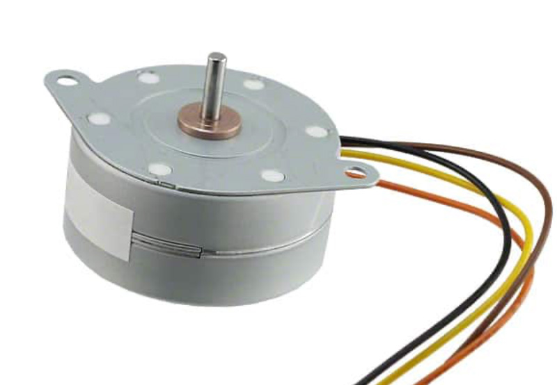
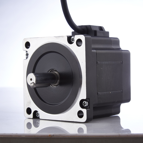
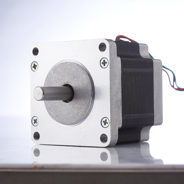
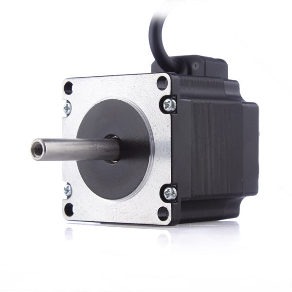
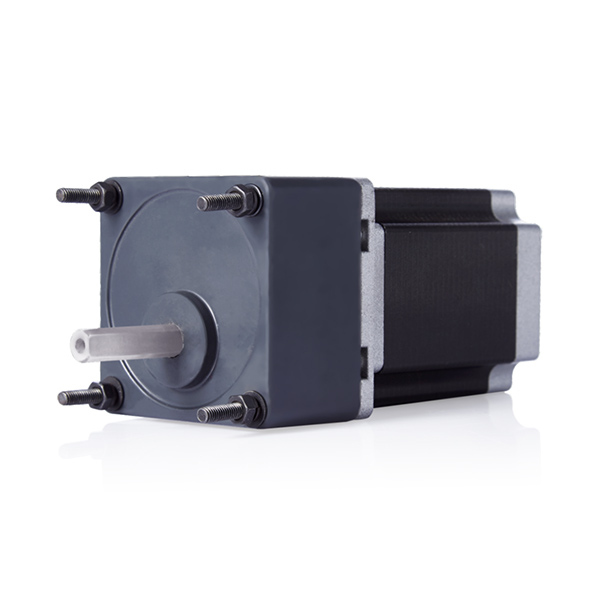
Figure 1: A typical PM stepper motor
The fundamental operating principle of a PM stepper motor is identical to that of a hybrid stepper motor. The key difference lies in the rotor: in a PM stepper motor, the rotor is made of permanent magnets. “PM” stands for “permanent magnetic.”
In a PM stepper motor, permanent magnets are arranged alternately around the outer circumference of the rotor, with north (N) and south (S) poles interleaved. The rotor surface is smooth and toothless (as shown in Figure 2). This design differs entirely from that of a hybrid stepper motor. Clearly, this configuration limits the number of pole pairs on the rotor—typically between 5 and 12—whereas the axial permanent magnet and toothed structure of a hybrid stepper motor allows for up to 50 (or even 100) pole pairs.
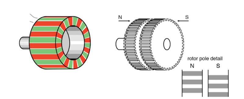
Figure 2: Rotor structure comparison—PM stepper motor (left) vs. hybrid stepper motor (right)
Now that we’ve covered the rotor, let’s examine the clever stator design of the PM stepper motor, as shown in Figure 3. Each phase has only one winding. On either side of the winding, there is a claw-shaped pole piece. The N and S pole claws interleave inside the winding. Magnetic flux lines are guided by these pole pieces, creating an alternating N-S magnetic field distribution within the winding.
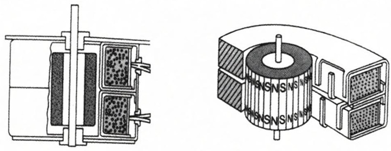
Figure 3: Cross-sectional view (left) and 3D cross-section (right) of a 2-phase PM stepper motor
Windings of other phases are coaxially aligned with the first phase but offset by a specific electrical angle. This offset angle (electrical angle) can be expressed as:
θ = 180° / P
where P is the number of motor phases. This electrical angle θ translates into the mechanical step angle of the PM stepper motor.
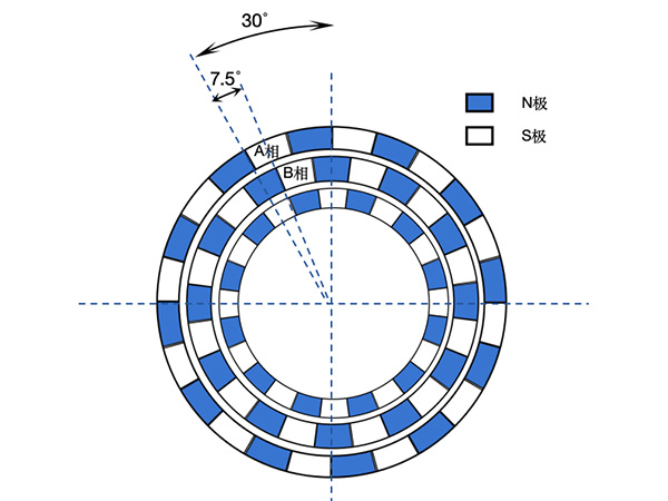
The structure of a PM stepper motor can be illustrated as in Figure 4. The two outer rings represent the two stator phases (for simplicity, the physically parallel and identically sized stator coils are drawn as concentric rings; in reality, the coils of different phases are coaxial and identical in size). The alternating blue-and-white blocks represent the interleaved pole claws, and the innermost ring represents the permanent magnet poles on the rotor. The number of pole pairs on the stator matches that on the rotor.
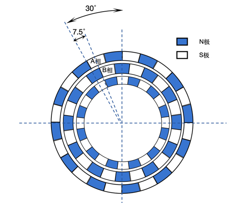
Figure 4: Schematic diagram of magnetic poles in a 2-phase PM stepper motor
Next, we’ll use a 2-phase PM stepper motor as an example, assuming both stator and rotor have 12 pole pairs.
According to the discussion above, the pole claws of phases A and B should be offset by an electrical angle of 180°/2 = 90°. Given that the rotor has 12 pole pairs, this corresponds to a mechanical angle of 90°/12 = 7.5°. Since each magnetic pole (N or S) spans 15°, the 7.5° offset means the two phases are shifted by exactly half a pole pitch (as shown in Figure 4).
So, how does a PM stepper motor rotate?
We energize the two phases in the following sequence: A → B → A⁻ → B⁻ → A. Here, “A” means phase A is energized in the forward direction, and “A⁻” means it is energized in reverse.
Assume initially that phase A is energized. In equilibrium, the rotor aligns as shown in Figure 5.
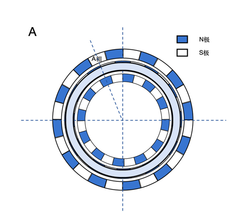
Figure 5: When phase A is energized, the rotor’s N poles align with the stator’s S pole claws of phase A
Next, we switch to energizing phase B. The magnetic field changes as shown in Figure 6 (left), causing the rotor to experience a clockwise torque and rotate one step angle—clearly 7.5°—to reach the new equilibrium position shown in Figure 6 (right).
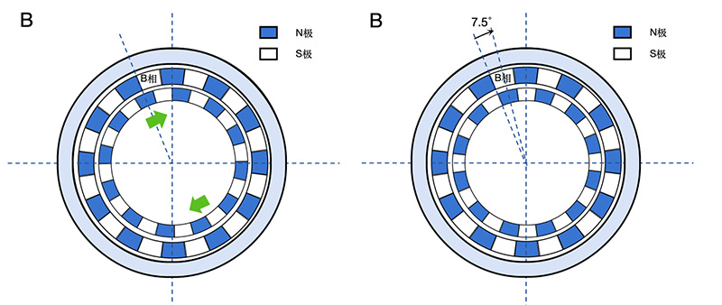
Figure 6: Magnetic field change and rotor torque when switching from A to B (left); equilibrium position after switching to phase B (right)
Then, we reverse the current in phase A (A⁻). The resulting magnetic field is shown in Figure 7 (left). Again, the rotor experiences a clockwise torque and rotates another 7.5° to the next equilibrium position (Figure 7, right).
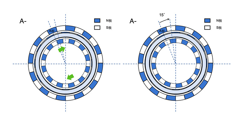
Figure 7: Magnetic field and torque when phase A is reversed (left); new equilibrium position (right)
In this way, continuous rotation is achieved by sequentially switching the phase currents.
The principles of two-phase excitation, half-step driving, and microstepping are identical to those used in hybrid stepper motors. For more details, please refer to our previous article on stepper motor drive modes and their underlying principles.
The above explains the structure and operation of a 2-phase PM stepper motor. What about motors with more phases? The core concept remains the same. Let’s take a 3-phase PM stepper motor as an example.
Structurally, a 3-phase PM stepper motor adds one more coil layer to the 2-phase design (Figure 8). The electrical angle between adjacent pole claws is 180°/3 = 60°. With 12 pole pairs, this translates to a mechanical angle of 5°. Thus, the step angle of a 3-phase PM stepper motor (with 12 pole pairs) is 5°.
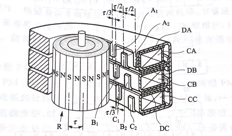
Figure 8: 3D cross-sectional view of a 3-phase PM stepper motor
The magnetic pole alignment between stator and rotor in a 3-phase PM stepper motor can be described as follows: the rotor’s S poles sequentially align with the N poles of phases A, B, and C, then with the N pole of phase A⁻ (which is effectively the S pole of phase A). Each step moves the rotor by 5°—the step angle.
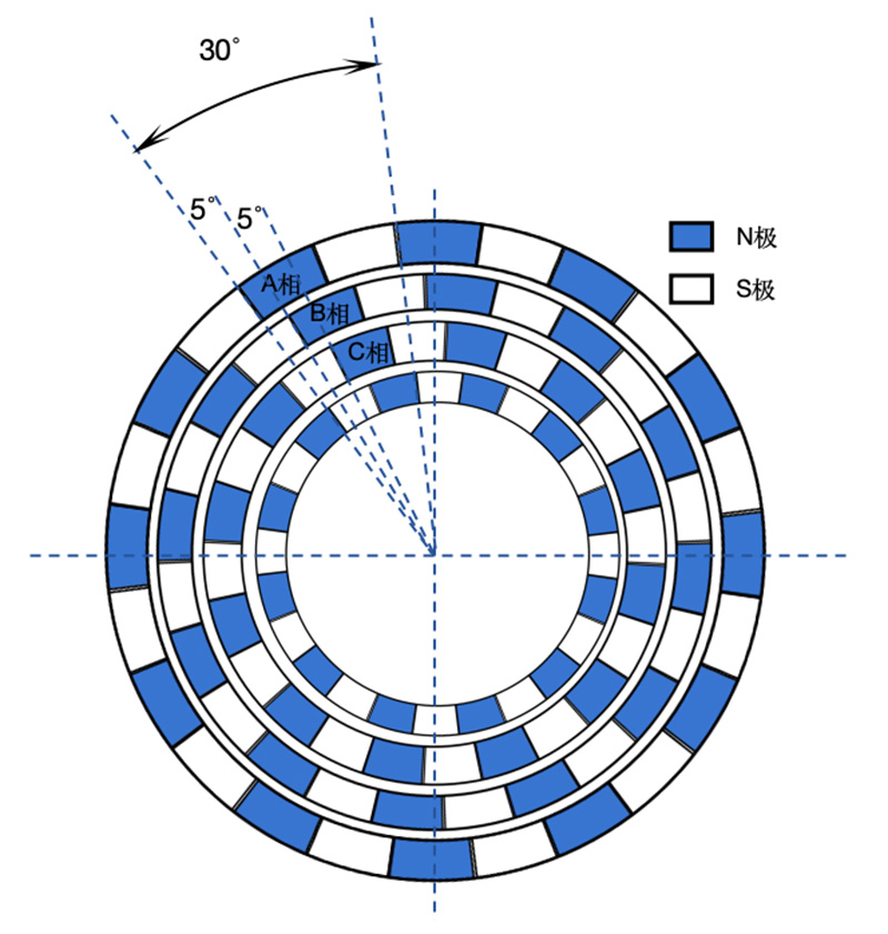
Figure 9: Schematic of magnetic pole distribution in a 3-phase PM stepper motor
In summary, compared to hybrid stepper motors, PM stepper motors offer two main advantages:
First, they lack the fine-toothed rotor structure, significantly reducing manufacturing complexity.
Second, each phase uses only a single coil, greatly simplifying the winding process (hybrid motors typically require 2–4 windings per phase).
As a result, PM stepper motors are much less expensive to produce. However, because it’s difficult to increase the number of magnetic poles on the rotor, PM stepper motors generally offer lower resolution (larger step angles) than hybrid types.
That concludes our overview of the structure and driving principle of PM stepper motors—a remarkably clever solution that achieves precise stepping motion using a simple and cost-effective design!